A PIR (Passive Infrared) Motion Sensor is one of the easier sensors to work with and is very straightforward to connect to a Raspberry Pi. The motion detector sensor itself has a sensitivity wheel that you can use to adjust motion sensitivity.
The IR sensor is typically encased in a “dome” which is actually has tiny “bubbles” that serve to scatter the beam to increase the motion detection range into a conical shape, rather than a simple straight-ish line.
For most applications and uses, this is definitely desired. If you think about a motion detector, you don’t want to detect motion in a narrow path – you typically want it to cover a wider area. The domes accomplish this purpose.
Let’s build the prototype.
Building a Raspberry Pi PIR Motion Sensor
The PIR sensor typically has 3 pins, which connects nicely to a 3-pin cable or even prototyping leads. One lead is positive, one negative and the other is the data cable. The data cable sends an electronic signal to a controller when motion is detected. The power is either 3.3V or 5V, depending on the sensor.
Wiring the Motion Sensor to the Pi is relatively simple. You can even do it without a prototyping breadboard.
Make sure the Raspberry Pi is powered off.
- Connect the data pin from the Motion Sensor to an available GPIO pin on the Raspberry Pi (We used pin 7)
- Connect the GND from the motion sensor to an available ground on the Pi Board.
- Finally connect the 5v power pin from the Pi to the sensor
That’s it. You now have a Raspberry Pi PIR motion sensor
Python Script for the Raspberry Pi PIR Motion Sensor
One of the advantages to using a Raspberry Pi for this type of development is you have a rich set of programming languages to choose from when writing the code to interact with your sensor.
We are going to use Python and the excellent Rpi GPIO that comes with the library for the Raspberry Pi to control the Input/Output pins.
Here is the simple script:
import RPi.GPIO as GPIO
import time

# Declare pin
pir = 7

# Setup GPIO inputs and outputs
GPIO.setwarnings(False)
GPIO.setmode(GPIO.BOARD)
GPIO.setup(pir,GPIO.IN)

try:
    while True:
        if(GPIO.input(pir)):
            print("Motion Detected!")
        else:
            print("No Motion Detected!")
        time.sleep(1)

# Gracefully cleanup and free the GPIO when user terminates the program by pressing Ctrl-C
except KeyboardInterrupt:
    print("Stopping")
GPIO.cleanup()Let’s walk through what we are doing.
We are simply importing the libraries we need in the first two lines. Line 5 declares the pir sensor data line entry point. Lines 8-10 are suppressing warnings, setting the mode to be Board, which we need to define the pir pin. Then, we are defining the pir pin as an INPUT as opposed to OUTPUT.
Finally, we get to the logic. We wrap the whole thing in a try block, so we can potentially catch exceptions and deal with them rather them letting them terminate the program in an unexpected or unhandled way. Line 13 starts a loop, which in this case is an infinite loop – it will run forever until we explicitly terminate the program.
Lines 14-17 handle the input of the pir pin. Simply stated, if the pir pin is sending a signal we can assume there is motion. In this case we print “Motion Detected” to the screen. Otherwise, we print “No Motion Detected”.
Line 18 pauses or delays execution of the next line. Since we are in a loop, the program will check if the loop needs to run again. Since we are in an infinite loop, the answer is always yes. So, we restart at line 14.
Finally, we catch the KeyboardInterrupt exception, which gracefully terminates the program. When you press Ctrl-C, this block will be triggered. We print a “stopping” message and call the cleanup function in the GPIO library, which releases the resources used including the pir pin reservation.
To run this, all we do is navigate to the directory on the Raspberry Pi where this script is saved and enter:
python3 pir.py
Follow the commit on github.com
Adding a switch and LED
Now that we have the basics, let’s make a couple of quick improvements. We will be adding a hardware switch to turn the unit on and off, and an LED to give a visual indication when there is motion detected so we don’t have to be watching our screen.
Here is the wiring diagram. We are using a prototyping board and some jumper wires to connect the components.
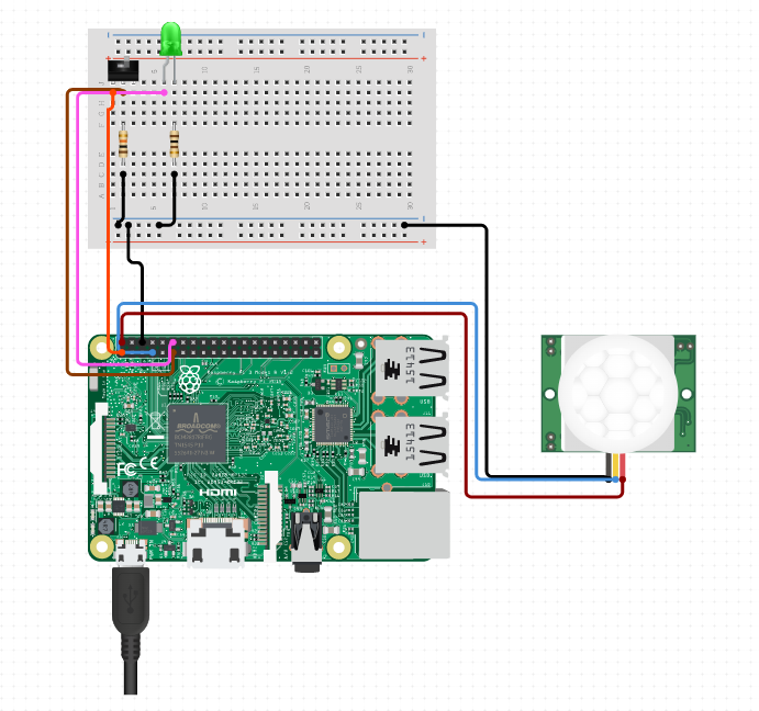
Mount the slide switch and led. Jumper the 3.3v output on the Pi to the first switch pin. On the second/middle switch pin, run a jumper to input pin 13, then a 10k Ohm resistor which connects to the negative bar.
For the LED, run a jumper from the input to pin 11. Connect a 100 Ohm resistor to the other lead of the LED, and connect that to the negative bar. Connect the negative from the pir sensor to the same negative bar. Then run a jumper from the negative bar to the ground (GND) on the Raspberry pi.
Modifying the Python Code
Now that the wiring is done, we need to make some code modifications to add the logic so the LED turns on, and the hardware switch controls the motion sensor.
import RPi.GPIO as GPIO
import time

# Declare pin
pir = 7
led = 11
gpio_switch = 13

# Setup GPIO inputs and outputs
GPIO.setwarnings(False)
GPIO.setmode(GPIO.BOARD)
GPIO.setup(pir,GPIO.IN)
GPIO.setup(led,GPIO.OUT)
GPIO.output(led,GPIO.LOW)
GPIO.setup(gpio_switch,GPIO.IN)

try:
    while True:
        while GPIO.input(gpio_switch)==1:
            # the switch is in the "on" position
            if(GPIO.input(pir)):
                GPIO.output(led,GPIO.HIGH)
                print("Motion Detected!")
            else:
                GPIO.output(led,GPIO.LOW)
                print("No Motion Detected!")
            time.sleep(1)
        # turn off the LED
        GPIO.output(led,GPIO.LOW)

# Gracefully cleanup and free the GPIO when user terminates the program by pressing Ctrl-C
except KeyboardInterrupt:
    print("Stopping")
    GPIO.output(led,GPIO.LOW)
GPIO.cleanup()Let’s review the changes highlighted. We added the led and gpio_switch variables and assigned them the pin values we connected to. We then setup the led as an output, and the switch as an input. We initialize the led to have LOW voltage output, which essentially turns it “off” to start.
We then adjust our while loop by adding another while loop that checks if the gpio_switch is returning anything. If it is, we can assume the switch is in the on position, and we can start checking if there is motion. If there is motion, we set the led output to be HIGH, which will illuminate the LED. If motion is not detected, we set the LED to be LOW, or off.
If we turn the switch off, we want to set the LED to turn off since we are no longer checking if there is motion. Finally, if we terminate the program using Ctrl-C, we turn off the LED (Line 34).
Follow the commit on github.com
Again, we can rerun by typing in the command line:
python3 pir.py
Try turning the switch on, then triggering motion. You should see text on the screen, and the LED should light up. Turn off the switch, and the LED should go out. Try triggering motion without turning the switch on. The LED should remain off, and the motion is not “detected”.
Hope you enjoyed this beginner’s tutorial on wiring and building a Raspberry Pi PIR Motion Sensor. In the future we will build more sensors, and eventually do something with the data that is being generated.
[…] up with several sensors to demo in order to feed a backend server module. An obvious choice was a PIR motion sensor, which is very straightforward and easy to build. Someone suggested a distance sensor, and having […]